White wire succses story!!!!

What the purpose of the WW is not absolutely clear.The most reasonable explanation is that shorting it to ground (black wire) will reduce the output to the CD unit enough to kill the spark,an engine stop output thereforeSome people appear to think that it is a light output (rather skimpy at that.).
It is actually an AC output which has a dc component, since the pos. cycle amplitude is a lot smaller than the neg. going one (due to loading from the CD unit).Furthermore it is NOT a continuous output either,rather short ac pulses with a duty factor of prob. less the 10%.Any cheapy digital multimeter will give meaningless readings,it can't handle this sort of input,all it tells you is that there is an output.
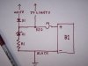
What can you do with the WW ?,without killing the engine of course..If you're in the money and can afford a battery sytem,a 12V battery can be charged with the WW,that extracts the most energy from the WW,you can also charge a 6V battery but that's not as effective.My 12 V peak to peak circuit(see previous posts) gets the max output &includes an optional overcharge indicator.A simpler version is just a neg going diode (band towards WW).This is also the best circuit for a 6V battery.A charge limiting resistor can be hooked up in series (20-50 Ohms) if desired
Running lights directly of the WW.There is not all that much power to be had,therefore the far more efficient LED's (5 times +) would make sense.More Lumens per Watt
The low-down on LED's,they behave like crummy diodes that is to say diodes with a large offset voltage,typically in the range of 2-4 V ,over that limit the current goes up rapidly and if not limited by a series resistor it would vaporise the thing.So if you connected a 3.5 V LED to a 6V battery with no resistance in the circuit you can kiss your LED goodbye.So what to do if you have a higher voltage?,string a nunber in series,sharing the current, that can work,if necessary with a series resistor if the current could get out of hand.The source resistance of the WW is about 2.5 Ohm,how much current an LED can handle in a pulsed mode depends on it's I squared x T ( I^xT) rating,if the pulse duration is halved,the max.current goes up not by 2:1 ,but only by 1.41:1,so the shorter the pulse the lower the average permissible current turns out to be
LED's in general cannot be put in parallel.If they are identical and from the same ultimate souce you can prob.get away with it.LED's like other diodes have a max.reverse voltage rating,they start to conduct but don't put out light but cause power waste & heat up the diode .So it's safer to put a diode in series to get rid of the negative cycle if you run them from a normal ac (The WW is NOT a normal ac source and you may get away with it since the reverse voltage is only 1/3 of the forward one.
LED's turn on and off instantly so they can flicker at low speed.
Incandescant lights,the WW will power a 6V 0.5A bulb but that's about it and may be able to handle a 6V front +3V taillight series combination,worth a try.12 V lights prob don't work as well (output voltage too low).Incandescants work on heating (power) &don't care about ac/dc or duty factor.
 
Last edited by a moderator:
donno what people are telling you all and i dont even have my engine yet
but i plan to add a simple bridge rectifier(or would a diode be better?) a cap and a led
133 hz flicker is hardly noticable
and hey, if i burn out a led or 2, i'll toss in a lm5505(5 volt regulator)
but a diode doesnt care if it gets 10 hz or 60 hz or 600 hz in most cases, it is more concerned about over voltage(a high voltage spike can kill a diode fast)
 
A bridge rectifier can work sort off,but not all that well for reasons you'll probably not readily understand, but NOTHING in the output circuit can then be grounded,that is you need a floating circuit.An LED likes to be operated from a 'current' source,something like the 'Buck Puck' instead of a voltage regulator,sticking them in series is a good way to get more light output if your peak output voltage is high enough, instead of wasting power in a voltage regulator.Read my previous post and try to understand it.
 
Last edited by a moderator:
I agree with duivendyk when it comes to trying to implement a full wave rectifier on these magnetos. There are a couple of issues that make it a poor choice. The requirement for an isolated ground bus is just one of them.

I implemented a 6v system that is working well. It keeps the battery fully charged and has overcharge protection. Since it has a battery, it lets me run large load items for periods of time. You can run LEDs, horns, turn signals, or incandescent lamps. It is modeled after the simple systems used on 1960's motorcycles. It has similarities to some of the other circuits discussed here.

Mine is a negative ground, half wave system and is correct for my particular engine. I have found that drawing power from a positive ground system is detrimental to the output of the CDI. Others have posted that positive ground is the correct way. This discrepancy leads me to believe that the polarities of the CDI may be different for different engines. Here is a simple way to test your engine. Hook a single diode to the white wire. While the engine is running, short the other end of the diode to ground. If the motor dies, reverse the diode and try again. The motor may slow down a tiny amount, but that is expected since we are putting a load on the alternator. It should not kill the spark/motor. If the line on the diode is pointing toward the white wire, you should implement a positive ground system, other wise, use a negative ground.

I'm surprised how well it is working out so far. I chose the lightest sealed lead acid battery that I could find, but any 6v motorcycle battery will also work. I posted this elseware on the site but this thread seems a good place to present it. Here it is:

WHITE - white wire from motor
RED - to light, horn, switches, etc.
BLACK - black wire to motor or to ground
D1 - rectifier diode, I used Radio Shack 276-1141
Z1 - zener diode, 6.8v, 5w - 1N5342B
R1 - power resistor, 10ohm, 5watt, I used Radio Shack 271-132
F1 - fuse, I used a 5 amp fuse
B1 - 6v lead acid battery, I used a 1.3ah SLA
Battery box - 2.0x2.5x5.0 plastic Radio Shack project box
Mounting brackets - plastic conduit clamps from Home Depot
 

Attachments

  • 100_0958.JPG
    100_0958.JPG
    147 KB · Views: 214
  • 100_0962.JPG
    100_0962.JPG
    70.5 KB · Views: 230
Last edited by a moderator:
It's quite possible that the CDI units could be different,but still somewhat puzzling to me,because there would be an ignition timing difference unless the CDI unit was engine specific. which is certainly possible.In the absence of a schematic I assume that the 10 Ohm resistor is a series dropping resistor between diode&battery ?.The peak voltages Etacovda once measured using a peak detector circuit werein the range of +7V / --20V at normal running speed.So you could run a 12 V system for more output capability,but it also gets a bit harder then to protect with zeners since the series dropping resistor would either disappear altogether or be much smaller (may be two 5W zeners in series across battery)
 
Duivendyk - On my last posting in this thread, the first attachment is a picture of the battery/component box mounted on the bike. There is a diagram of the circuit in the second attachment. The 10ohm resistor is in series with the zener to provide a softer voltage clamp. I could probably eliminate the resistor and still be fine. Actually, if the 6v battery is a large enough, you can also eliminate the zener regulator and resistor. The charging circuit has a fairly small output and lead acid batteries can stand a limited amount of overcharging without damage. A wet cell motorcycle battery is even more forgiving. I wanted to use a very small, sealed battery, hence the regulator.

I'm not sure about the 12v system. Before I designed my system, I put a capacitor across the rectified output of the white wire. I only got about 8 or 9v peak by revving the motor some. I may have been able to get over 12v while driving at high speed but I did not test that. Even though it may be capable of producing slightly higher peak wattage at 12v, it may suffer when trying to charge a battery. I think I can get a better average output using 6v since it works across a much larger rpm range. On my simple circuit, I'm only using half the wave form. And the only part of the sine wave that actually charges the battery is the peak portion that is over 6v. The area of the sine wave that is over 12v is much smaller in general and is absent at low rpms. Maybe it has to do with the specific alternator. Better to err on the low side (6v) and just waste a little bit of wattage. If we err on the high side, the battery may not charge.

You said the Etacovda got +7v/--20V at normal running speeds. Is that the upper and lower half of the sine wave? That might explain our differing conclusions on which voltage to use. I'm using the positive 7v portion of the wave. From my earlier reading of this thread, I believe that he may have been using the negative portion, so had a higher voltage to work with.

I would be interested if others could do the shorted diode test to see which direction kills their running motor. I used a 5w rectifier diode for the test and did not burn it out. That would give us some data points to determine if the polarity of the CDI is random or mine is non-standard.
 
Last edited by a moderator:
Yes that's what sticks in my mind,I'm really more a sidewalk superintendant,I coached Eta in making these peak output V measurements prescribing time constants to get reasonably values.My guess is that the duty factor ofte ac pulse is less than10% so the peak curent values are fairly high at least a few Amps.If you had an old fashioned analog reading meter,the average dc voltage reading would be negative (for negative output)but not all that much because of the low duty factor).I concocted a peak to peak(voltage doubling circuit) but takes 2 diodes and 2 good sized caps 330MF 35V+.Put out 5/6W at 12 V according to Eta,but he seems to have disappeared from the scene for quite some time.I posted a schematic of it in an exchange with a guy in Sydney.Impression was his nom de plume I think.But he must have headed for the outback too.The source resistance of the WW is 2.5 Ohm which does not seem like a lot but at 2A it's 5V drop.That 6.7V will keep the batt V at that level,will reduce charge current some but is a load on batt during the rest of duty cycle,so more effective than it looks.May be should consider Schottky diode in series with zener, good for another 0.3 V to 7.0V
 
I'm going to leave it the way it is for the time being. It is simple, troublefree, and has been working well. I have 360 miles on the bike now. The zener/resistor regulator is designed to rapidly taper the charge once it reaches about 6.8v. The charge system leaves the battery at about 6.4v (after rest with motor off). The only load that it experiences on a regular basis is the stoplight. If I use the headlight/taillight much, I have to do a couple hours of daylight driving to get the resting voltage back up to 6.4v.

I'm satisfied with it now. Except I still want to learn more about the positive vs. negative ground differences present in these motors.
 
Last edited by a moderator:
Scotchmo, I'd like to know how much light you are getting from your system, especially your head lamp. Can you post a video to demonstrate this, maybe at night? Mike
 
Back
Top