HappyTime 2 Cycle Ignition Circuit Explained with Diagram

Status
Not open for further replies.

VTBikeman

Member
Local time
7:38 AM
Joined
Aug 28, 2008
Messages
38
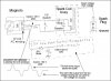
As promised: A schematic of the HT ignition circuit and some musing.

The magneto (generator, alternator) has 2 poles. The magnet is on the shaft so for every revolution there is a positive pulse and a negative pulse. The diode selects the pulse as the piston nears tdc and blocks the pulse that is made as the piston nears bottom dead center. The voltage I measured is about 120 volt peak and probably goes up with RPM. I used a drill to spin the motor with the plug out to measure this.

The capacitor tunes the coil to resonate at a frequency that will give the coil's highest output.

That actually leaves the negative half of the wave unused and if you use a half wave rectifier you should be able to tap some power off that low voltage winding to do something like charge a few batteries without affecting the spark. I didn't measure the output of that winding yet but the published spec is 6 volts or so that could yield a DC peak voltage of about 8.4 volts, not enough to charge the batteries (12v) on my bike directly.I also do not know which polarity you would get. You may wind up with a negative supply (pos ground) which is no big deal unless you've grounded your electric system as neg ground. You could probably still pull 3 watts off that winding without harm as you are using it 1/2 time. Feed a small dc:dc inverter and there's your battery charger.

There is no scr because there is no separate trigger for it. The spark is generated solely by the magneto.-simple and elegant. Could a CDI be built for it with the oem alternator? Probably but you would need a separate detector to trigger the spark and one end of the magneto is grounded so the choice becomes a 1/2 wave rectifier or a voltage doubler to charge the big C. Once you have the cap charged up then the motor would start.

There are some CDI schematics on line that use a microprocessor to advance the spark at higher rpm's but from the curve the advance doesn't kick in until 5K rpm's and now your up to the upper limit of the engine anyway. Has anyone studied spark advance for that motor? Maybe it would help at a lower rpm's.

I Hope this helps.
 

Attachments

  • HappyTime Motor Ignition ckt.jpg
    HappyTime Motor Ignition ckt.jpg
    66 KB · Views: 31,599
I am thinking that there has to be more to the ignition than that.
Reason is that there needs to be something triggering the spark, as just connecting it to the magneto (even with diode and cap) will just produce a spark whenever the voltage potential reaches approx 2600 Volts to the plug. (using 75,000 volts for a spark to jump a 1 inch air gap) So as the engine RPM increases the timing will be greatly affected as magneto voltage output rises. If this is all that is needed for an ignition system, we would have seen breakerless ignitions in small engines and motorcycles in the 50's and 60's when silicon rectifiers became inexpensive and in widespread use.

I am thinking that there is some sort of solid state device (transistor/SCR) that is triggering on the falling edge of the waveform. If you look at a magneto on a weed whacker or lawn mower engine, there is no separate trigger coil unit. Just a coil and associated electronics all in one, with the spark triggering done by simple wave form processing.
 
Well, there are no more wires than what I showed and I took some measurements to confirm the presence of a diode and someone else reported the presence of a cap so I drew what I thought was in the box.

I get resistance measurements that confirm uninterrupted circuits in the magneto and the box. Maybe there's an SCR that triggers at some point but if that were so I wouldn't get a constant diode drop (.512v) when measuring the input to the device. The cap would charge to a volt or so and the current would stop.

The spark starts when the magnetic field collapses in the spark coil, not when it is fed. If that cap charges up to the peak voltage then the collapse starts as soon as the input goes below the charge voltage as the diode blocks any reverse current. The cap discharges into the coil and then the field collapse starts.

All the lawn mowers I grew up with had a magneto with the magnet on the flywheel with the spark wire going right to the plug and a switch attached to the throttle to short some turns to kill the motor. No timing issues as it was made to run at a constant speed.

The only difference here is that the spark coil is outboard in an epoxy box, like a HV supply in a tv. Probably cheaper and safer and more reliable this way. We do have modern insulators available now.

Remember- this is an engine that costs very little money. It only has to work, not work great. I'm amazed it works as well as it does.
 
Last edited:
......All the lawn mowers I grew up with had a magneto with the magnet on the flywheel with the spark wire going right to the plug and a switch attached to the throttle to short some turns to kill the motor. No timing issues as it was made to run at a constant speed.....

Right, but there was a set of points to precisely time the collapse of the magnetic field and produce a spark.

Producing a spark the way you describe is easy, but timing it precisely enough for an engine to run well over a wide RPM range (1500-5000+RPM) is a different story.

There has to be more in that box IMO.
 
I think the diode gives it the precision as it shuts off the magneto current when the magneto voltage drops below the capacitor voltage. Then the cap has to discharge through the coil. The cap will charge before the coil conducts as the coil resists a change in current, the main characteristic of inductance.

Now that I think of it lawn mower engines did have points but as a 4 cycle engine with 1 magnet flying around the magneto it had to fire on ALTERNATE revolutions and it ran off the camshaft which turns at 1/2 speed the speed of the crank. I don't think it did critical spark timing functions. I think it just killed the spark on the exhaust-intake cycle.

There has to be a small engine repairman out there who can set this straight.

If you have an extra box take it apart. I'd love to see it. I went on what I could measure and what others had to say about what's in the box. There is certainly a diode voltage drop and it is continuous indicating the circuit I provided is consistent with the measurements.

A small B&S engine with points/condenser magneto ignition fires every revolution. The points are opened and closed by an eccentric on the crankshaft, not the camshaft. The points are under the flywheel. It actually fires during the exhaust stroke too, but nothing happens. A lot of cars do the same, it's called "waste firing". (for example, a six cylinder engine with 3 "direct" ignition coils, two plugs per coil - one cylinder fires on compression stroke, the "sister" cylinder fires simultaneously on the exhaust stroke.) The breaker points perform the essential function of interrupting the current through the primary of the ignition coil, causing the magnetic field to suddenly collapse and generate the high voltage pulse in the secondary winding. For the ignition coil to function, the power must be "pulsed" in this manner whether it be from mechanical breaker points, a transistor, or an SCR dumping the charge of a capacitor. (CDI) The "tuned circuit" you theorized would not work for an ignition application.

The "diode voltage drop" you are seeing can be caused by any number of solid state components. A pocket radio will give you about the same reading, and there is much more to a radio than a diode, capacitor and transformer.

In another thread, someone hacked apart a HT ignition module and posted pictures. I think the results were inconclusive because everything was still basically covered in epoxy.
 
HI,

Just curious, but with everybody looking for better ignition strength and more power to run lights etc....How hard would it be to modify the HT engines to make 12V power at some acceptable wattage?...Is it as simple as messing with the windings (as in adding more?).

Andrew
 
I'm working with a local generator/starter shop to rewind the coil to produce 14V,and run a motorcycle CDI unit and 12V lighting. The tech at the shop says I should get about 30 watts output. I plan on using a trail bike rectifier/regulator and a small lead acid battery. The CDI is less than 20 bucks, but it will require me to rig an external trigger coil and sensor magnet to the HT engine.
 
I hooked the box up to an isolation transformer and a variac and took wave forms for input voltage and input current at an input voltage that creates a spark, about 80 volts ac at 60 sparks/sec. Gives about 1/8-1/4" spark.

The spark timing is independent from the input voltage and starts at the end of the charging cycle that uses the negative half of the power wave from the alternator. The cap is charged during that cycle and it is fired, probably via an scr, after a fixed delay from the end of the charging cycle. The timing may be accomplished with a cheap timer chip or a microprocessor or some other method. This syncs the spark to the output of the alternator independently of the voltage.

I'll drive the isolation transformer with an audio amp and see what happens to the timing vs frequency.

This is indeed more sophisticated than I thought. I am going to retract and redo the circuit. What's in the box has to be diagrammed in block diagrams since it is potted in epoxy. There are different ways to do the timing in either the analogue or digital domain.

It is indeed a CDI and I have the wave forms to show it. I just don't have the circuit in the black box.

You are correct about waste firing on a 4 cycle engine.
 
Wow - great work VTBikeman! I like your idea of driving it with an audio amp and signal generator, this way, you can test if it has some sort of rev limiter without putting your engine at risk!

As far as what is inside the box, I doubt there is any embedded processor considering how inexpensive they are. I just think there is a diode, capacitor, and SCR and a few other components (maybe a R/C network and a transistor) to trigger the SCR on the falling edge of the AC wave form. (after the cap is charged) If there is any timing advance, it is probably done with the SCR trigger circuit and not with an "intelligent" processor.
 
Status
Not open for further replies.
Back
Top