Flattracker
Member
- Local time
- 5:38 PM
- Joined
- Dec 4, 2009
- Messages
- 84
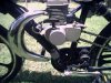
 I guess my last posts got deleted in the server change over so here are the photos again of the Chinese made 50 watt permanent magnet mini alternator model YAF-54 and the mounts that I designed and built for holding the alternator and the rear tail/brake light and turn signals.
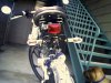
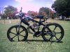
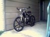
 I wanted a self charging lighting system so I bought two 12V 2.2 ah SLA batteries wired them in parallel, and strapped them to the main downtube with black duct tape to hold the connections and to try to camoflague the electronics. You can see them in the photos they're black right under the front signal lights.
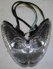
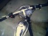
My bike features a 12V electrical system with a 25/18 watt chrome plated visor hi/lo headlight, a 12V motorcycle horn, a chrome plated brake/tail light, and four chrome plated "cateye" amber colored turn signals with clear lens, and last of all a 50 watt 6 amp alternator to keep the batteries charged. There is no master on/off switch on my electrical, or charging system. It is not required. The batteries route directly to the regulator and power flow is fixed by the regulators inner diodes so there is no power drain on the batteries. It also has a modified chain idler using a #41 steel idler sprocket attached to the upper chainstay using a manual transmission clutch return spring. This setup allows me to use the dual suspension frame without the chain jumping off the sprocket when I hit bumps. This bike rides surprisingly smooth on its 2x2.125 Kustom Kruiser Fireball tires. Almost as smooth as a real motorcycle with no noticeable vibrations! Its an actual pleasure to ride!
No more batteries to deal with! No more riding home in the dark because of dead batteries. If the SLA's ever need recharging they are charged by disconnecting the red and black DC output wires from the regulator and connecting them to a charger (they're connected directly to the batteries). I use a 15w solar panel.
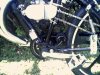
A common scooter voltage regulator/rectifier regulates the alternator output, and is seen strapped to the lower main downtube next to the alternator
I wired in a main fuse for the lighting system and one for the alternator.
The tire drives the alternator at a 10.4:1 ratio and it will produce 6 amps at 3000 rpm! You wont get this ratio using pulleys unless the pulley is as large in diameter as the wheel!
This system is independent of the engine, and only generates power when the wheel is turning. This means that it can be applied to ANY bicycle motorized or not! Well, at least if the bicycle has room between the seat post and rear tire. I can see all those custom lowriders now with an alternator!
There is very little drag from the alternator. The engine has WAY MORE drag on your bike than this alternator, and you probably wont even notice it while pedaling your machine.
At a wheel rotation of 350 rpm, the alternator rotates at 3640 rpm. 350 rpm translates to about 10 mph in actual ground speed on a 26 inch bicycle.
Thats PLENTY of power to wire just about anything you want to your bike. At motorized bicycle speeds the alternator gets hot, depending on how fast you ride, your alternator may reach speeds of 9000 rpm or more! I was surprised at the heat generated by my alternator during my first full speed test run! This is normal.
The alternator has a pulley at one end but it is cast or machined into the uni-body case/housing and does not rotate independently. The whole outer case/body rotates around a center shaft. This one piece body construction allowed me to devise a superior method of driving it which is against the tire as opposed to the pulley system. My system allows the alternator to reach its highest maximum possible speed
There is a small rubber R/C car tire stretched over the alternators body to help grip the tire and to protect the case from contact damage.
Now you can get the benefits of a full fleged motorcycle lighting system! I included the links to the alternators manufacturers specifications. Check out my mounting system.
As before, my system is unique. This is my idea, I thought of these mounting systems for my alternator, and tail/brake light. First conceived by me, designed by me, built by me, and tested by me.
I bought the alternator on ebay from the seller "motorzhao"
Here is a link to the manufacturer with the alternators specifications.
http://www.small-generator.com/
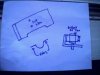
The alternator is 3 inches in diameter and a mounting bracket is cut from a .25 inch piece steel plate 3x5-6 inches long, and is "L" shaped (see drawing). You'll need to heat the metal bright orange hot to bend it (propane torch). A bench vise works for the holding and hammering.
A pencil tracing of the alternators base mounting holes is transfered to the metal strip you cut, taped on, then drilled. Drill the center hole for the power leads large enough to run a wire loom through it. This will help secure, and protect the wires from damage.
The side of the bracket that faces the tire must be notched to keep the tire from rubbing the metal lip of the bracket and to get a tighter contact with the tire.
THIS IS MY IDEA.
PLEASE RESPECT THIS.
FEEL FREE TO USE THIS IDEA FOR YOUR OWN PERSONAL BICYCLE.
IT IS NOT INTENDED TO BE USED FOR PROFIT OR COMMERCIAL GAIN.
ANY VENDOR, SELLER, PERSON, ENTITY, CORPORATION, MANUFACTURER THAT ILLEGALLY STEALS MY IDEA OR ANY PORTION OF MY IDEA(S) FOR THIS TYPE OF MOUNTING FOR THIS TYPE OF ALTERNATOR WITHOUT COMPENSATING ME IN ADVANCE, WILL BE PROSECUTED THROUGH THE COURT SYSTEM TO THE FULL EXTENT OF THE APPLICABLE LAWS UNDER US CODE.
ANY WISH TO USE MY IDEA FOR PROFIT MUST BE MADE FIRST, IN WRITING, IN ADVANCE OF ANY PROFITABLE ENDEAVOR OR MANUFACTURING PROCESS.
Attachments
Last edited: